Pile Cap - Results
The locations for output for pile caps are the Pile Cap Design Results Spreadsheet and the Pile Cap Detail Report.
Pile Cap Design Spreadsheet
To view the Pile Cap Design Spreadsheet, click Results Browser from the Results toolbar and click Pile Cap Design. Or, click Pile Cap Design from the Results section of the Explorer panel. These output browsers are meant to summarize the results for the pile cap. For more information on the pile cap results, select Detailed Report from the Results ribbon (when in a graphical view) and click on the pile cap you want to review.
Pile Cap Code Checks
Click on image to enlarge it
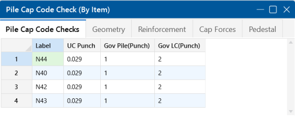
The Pile Cap Code Checks tab gives the worst case pile for the worst case load combination for the punching shear code check.
The rest of the pile design checks including shear, compression, tension and punching shear are in the Pile Design Spreadsheet.
Pile Cap Geometry
Click on image to enlarge it
The Geometry tab of the spreadsheet provides dimensions for the pile cap and pedestal. To get a detailed sketch of this information, see the Detail Report.
Pile Cap Steel Reinforcement
Click on image to enlarge it
The Reinforcement tab of the spreadsheet gives the required steel for both the pile cap and pedestal. For more information on the design of the pile cap reinforcement, see Pile Cap - Design and the Pile Cap Flexural Design portion of the Detail Report.
Pile Cap Design Forces
Click on image to enlarge it
The Cap Forces tab of the spreadsheet provides a summary of the forces in the pile cap for the worst case load combinations. The Muxx and Muzz moments are the worst case moments from the positive and negative faces of the pedestal in both directions. They are based on the local axis of the pile cap, which can be displayed using the options in the Model View Settings. For more information on these design values, see Pile Cap - Design and the Pile Cap Flexural Design portion of the Detail Report. Vu-pis the pedestal punching shear demand. For more information, see Pile Cap - Design and the Pedestal Punching Shear portion of the Detail Report. The Vu-x and Vu-z shears are the worst case shears from the positive and negative faces of the pedestal in both directions. For more information, see Pile Cap - Design and the One Way Shear portion of the Detail Report.
Pedestal Design Checks
Click on image to enlarge it
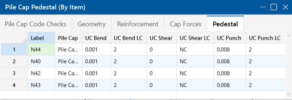
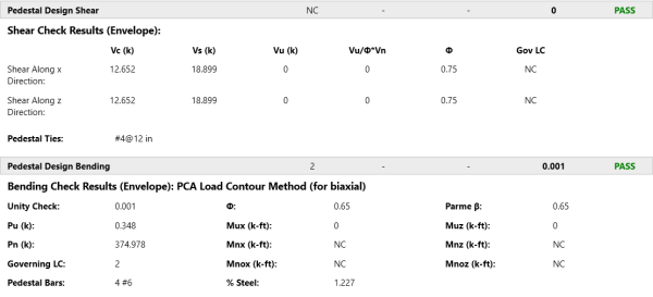
The Pedestal tab provides a summary of the design checks for the pedestal for the worst case load combination. For more information, see Pedestal - Design and Punching and the Pedestal Design portion of the Detail Report.
Pile Cap Detail Report
The Pile Cap Detail Report provides detailed information about geometry, materials, criteria, design checks and sketches associated with this pile cap. Below, we will walk through each section of the report.
Header
Click on image to enlarge it
The header of the Detail Report is useful for navigating and viewing information in the pile cap reports.
- The arrows allow you to click through detail reports for the different pile caps in the model.
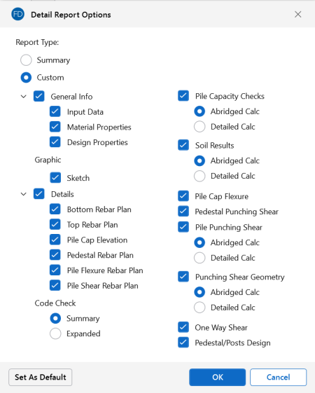
- The Options button opens up the Detail Report Options dialog. This allows you to customize exactly what you see in the Detail Report. Some Code Checks have an option to show either the Abridged Calc or the Detailed Calc. We will talk more about this in the following sections.
Click on image to enlarge it
Input Data, Material Properties and Design Properties
Click on image to enlarge it
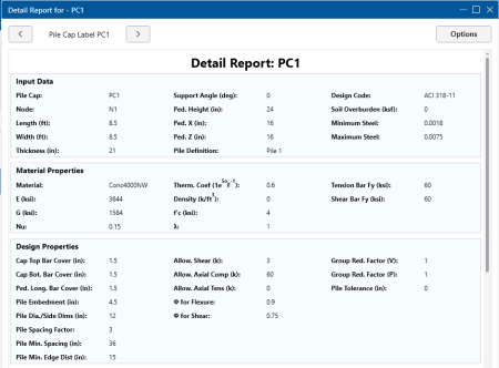
The Input Data lists off the point label of the pile, material properties, reinforcement properties and design requirements, as applicable from the Design Rules, Pile Definitions, Pile Cap Definitions and Pile Caps Spreadsheets.
Sketch
Click on image to enlarge it
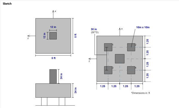
The Sketch section provides a full sketch of pedestal and pile locations. The dimensions are given using the CRSI pile layouts, edge distance, pile spacing factor and the pile diameter/side dimension. The minimum distance between piles is defined by the Spacing Factor x Pile Diameter/Side Dimension and is shown on the sketch as well (SF*D).
Reinforcement Details
Click on image to enlarge it
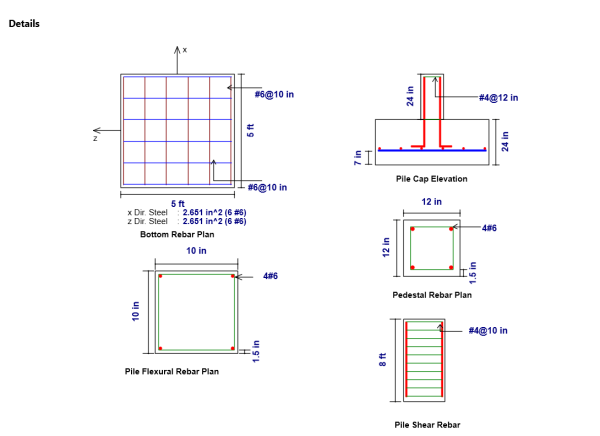
The Reinforcement Details section lists bar size, spacing and total reinforcement in each direction of the pile cap. If welded wire reinforcement is designed, the output result will be preceded by a “D” instead of “#” to indicate the wire bar size. This gives you a to scale visual of the reinforcement in your pile cap, pedestal, and concrete piles. For more information on the required steel calculation, see Pile Cap - Design and the Pile Cap Flexural Design portion of the Detail Report.
Pile Capacity Checks
Click on image to enlarge it
Click on image to enlarge it
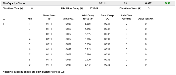
The Pile Capacity Checks section can be shown in two ways by selecting between the Abridged Calc and Detailed Calc options in the Detail Report Options dialog. The detailed view (top) gives forces and code checks in each pile in the pile layout for each service load combination run. The abridged view (bottom) simply gives the maximum code check for the worst case pile for the worst case LC. To learn more about how these forces are calculated and how the allowable forces are modified, see Pile Caps - Design.
Soil Results
Click on image to enlarge it
Click on image to enlarge it
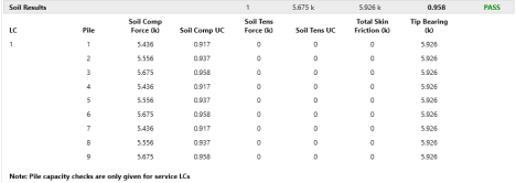
The Soil Results section can be shown in two ways by selecting between the Abridged Calc and Detailed Calc options in the Detail Report Options dialog. The detailed view (top) gives forces and code checks in each pile in the pile layout for each service load combination run. The abridged view (bottom) simply gives the maximum code check for the worst case pile for the worst case LC.
Pile Cap Flexural Design
Click on image to enlarge it
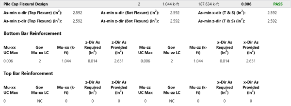
The Pile Cap Flexural Design section starts by giving minimum steel requirements for both flexure and shrinkage and temperature. Then there is a bottom and top bar reinforcement section where the max moments at the face of the pedestal is given in both orthogonal directions. The Muxx moment (moment causing bending about the x-axis) is the maximum moment computed considering all strength load combinations at both the positive and negative z faces of the pedestal. Top reinforcement is only added if there is negative bending in the pile cap. For more information on reinforcement calculations, see Pile Caps - Design.
Pedestal Punching Shear Check
Click on image to enlarge it
The Pedestal Punching Shear Check section provides the demand punching shear and moments at the base of the pedestal. These forces are then converted into an equivalent total stress and this stress is reported.
Phi*Vny represents the shear stress capacity of the slab calculated based on the three ACI equations for two way or punching shear capacity of the slab. This value does NOT include any additional capacity due to shear reinforcing in the slab. For information on the calculation of the punching shear demand, see Pile Caps - Design. For information regarding geometry, see the Punching Shear Geometry section of the Detail Report.
Pile Punching Shear Check
Click on image to enlarge it
Click on image to enlarge it
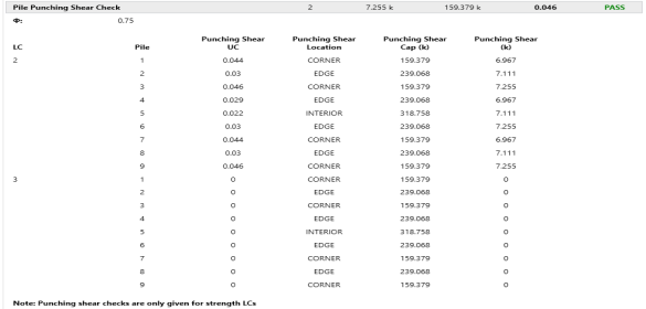
The Pile Punching Shear Checksection can be shown in two ways by selecting between the Abridged Calc and Detailed Calc options in the Detail Report Options dialog. The detailed view (top) gives forces and code checks in each pile in the pile layout for each strength load combination run. The abridged view simply gives the maximum code check for the worst case pile for the worst case LC. To learn more about how these forces are calculated and how the allowable forces are modified, see Pile Caps - Design.
Punching Shear Geometry
Click on image to enlarge it
Click on image to enlarge it
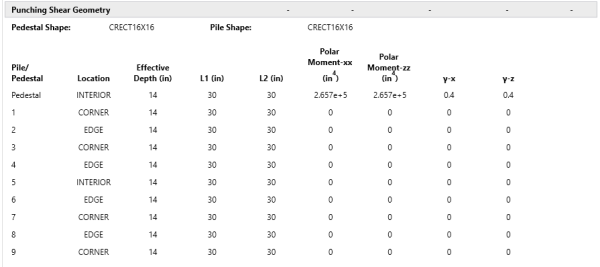
The Punching Shear Geometrysection can be shown in two ways by selecting between the Abridged Calc and Detailed Calc options in the Detail Report Options dialog. The detailed view (top) gives geometry information for every pile. The abridged view (bottom) simply gives the geometry information for the worst case pile.
Location
The pile and slab geometry is investigated and checked for all three types of punching failure (Interior, Edge and Corner). This field represents the type of failure method that controlled the code check calculation.
L1 and L2
Length of the critical section along the local axes. This value is used to define the punching shear perimeter, as well as to define how much of the moment is transferred by eccentricity of shear (as opposed to the portion transferred by flexure).
Polar Moment - xx and Polar Moment - zz
This is a property (Jc) of the critical section which is analogous to polar moment of inertia about the local xx and zz axes. This value is used to determine the shear stress in the critical section which is due to unbalanced moment.
Gamma x and Gamma z
This is calculated from the dimensions of the assumed punching shear perimeter. It represents the fraction of the unbalanced moment for each axis that is transferred by eccentricity of shear.
See Pile Caps - Design for more information about geometry considerations in the Code Checks.
One Way Shear Check
Click on image to enlarge it
The One Way Shear Check section provides a results summary for beam shear across the pile cap. The x-Dir Cut Vu displays the worst case shear force at the positive and negative x sides of the pedestal for all strength LCs. The Vc (x-Dir Cut) and Vc (z-Dir Cut) gives the shear capacity about both local axis directions. The w, d, Vu and Mu-xx and Mu-zz values are given to verify the calculation of shear capacity. For more information on these calculations, see Pile Cap - Design.
Pedestal Design Checks
Click on image to enlarge it
The Pedestal Design Shear and Pedestal Design Bending sections provide design check results for both shear and combined bending and axial forces. For more information on these checks, see Pedestals-Design Results.
